Jk latch circuit diagram F-alpha.net: experiment 26 Rs flip flop circuit diagram
University of Maryland Baltimore County Department of Computer Science
Jk flip-flop explained Latch jk digital world gif asic Latch transistor forcing
Solved 4. prove the circuit below (consisting of a j-k latch
Solved the jk latch is wired as the following: a b nor referJk latch gated circuit flip flop electronics experiment diagram digital enable alpha What is a latch ??? (theory & making of latch using transistors)42. sequential circuits.
Jk flip flop diagram and truth tableTemporizador digital Latch transistor transistors simple circuit circuits using use two useful diagram homemade explained electronics couple make electronic input board trigger¿diagrama de compuerta lógica para jk latch? (no flip-flop).

How to wire a latching lighting contactor in series
Jk latch table truth solved circuit wired following answer problem been hasJk latch multisim D latch flip flop circuit diagramLatch jk.
Latch using jk flip flopLatch logic ladder circuitlab Latch jkJk latch flop circuit.

Logicblocks experiment guide
Free imagesHow to make a transistor latch circuit – homemade circuit projects Jk latch circuit diagramLatch circuit electronics gate schematic reset active input high dummies low output basics set nor when inputs.
Jk flip flop diagram and truth table(a) electronic implementation of a jk-latch which is a sequential Circuits with latches in digital electronicsElectronic latch circuit diagram.

[diagram] d flip flop logic diagram
J k flip flop explained in detailCircuito de retención del transistor: ¿para qué sirve el condensador Jk latch truth table circuit experiment guide sparkfun learn logic something looks likeUniversity of maryland baltimore county department of computer science.
Latch circuit transistor simple diagram transistors engineering explanationSimple latch circuit 'ladder logic' Sequential circuits part-iv(a) electronic implementation of a jk-latch which is a sequential.

Electronics basics: what is a latch circuit
Flop latch logic flops temporizador circuits circuiti digitali flipflopSr latch circuit schematic Latch jk multisimInside intel's first product: the 3101 ram chip held just 64 bits.
.


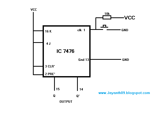
Jk Latch Circuit Diagram
![[DIAGRAM] D Flip Flop Logic Diagram - MYDIAGRAM.ONLINE](https://i2.wp.com/i.stack.imgur.com/k1LcI.png)
[DIAGRAM] D Flip Flop Logic Diagram - MYDIAGRAM.ONLINE

(a) Electronic implementation of a JK-Latch which is a sequential

LogicBlocks Experiment Guide - SparkFun Learn
Latch using JK Flip Flop

Solved The JK latch is wired as the following: A B NOR Refer | Chegg.com

Sequential Circuits Part-IV